UGO of telecommunication systems
Content: 41023161508410.rar (1.09 MB)
Uploaded: 23.10.2014
Positive responses: 1
Negative responses: 0
Sold: 51
Refunds: 0
$3.32
A collection of conventional graphic symbols for expert design of telecommunications, computer, and other IT systems of varying complexity.
Contents:
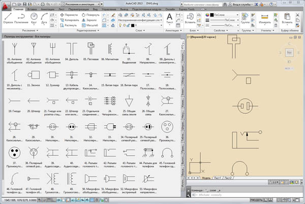
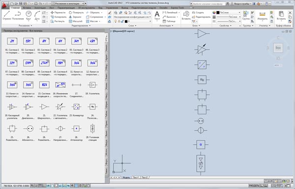
1. Conventional graphic symbols for telecommunications systems used in international practice. Based on the book "Secrets of Foreign Circuits" by V.S. Yatsenkov, 2004.
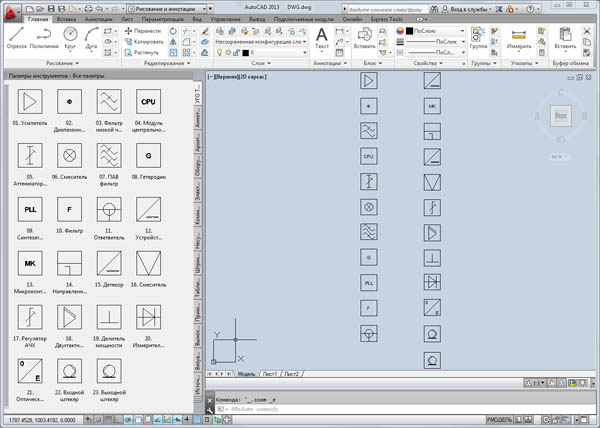
2. Conventional graphic symbols for telecom components: interface converters, clock system equipment, RJ connectors, interface cables, Cisco Systems equipment.
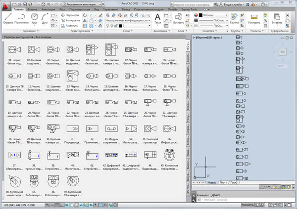
3. Conventional graphic symbols for television broadcasting systems. Developed using PLANAR´s "PLANET 1.4" cable television network calculation software.
4. Conventional graphic symbols for fiber optic systems. According to GOST 2.761-84 "GOST 2.761-84 Unified System for Design Documentation. Conventional Graphic Symbols in Schematics. Components of Fiber-Optic Transmission Systems."
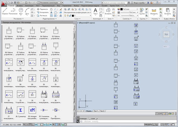
5. Conventional graphic symbols for telemetry devices. According to GOST 2.752-71 "Unified System of Design Documentation. Conventional Graphic Symbols in Schematic Diagrams. Telemetry Devices."
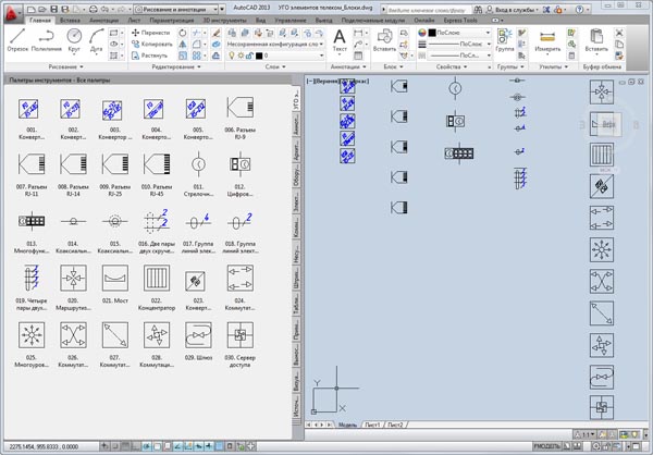
6. Conventional Graphic Symbols for Telecom System Elements:
GOST 11216-83 "Distribution Networks of Television and Radio Broadcasting Receiving Systems. Main Parameters, Technical Requirements, Measurement and Test Methods."
GOST 2.766-88 "Unified System of Design Documentation. Conventional Graphic Symbols in Electrical Circuits. Time-Division Multiplexing Information Transmission Systems."
7. Conventional Graphic Symbols for CCTV Systems.
Format – DWG.
7 Conventional Graphic Symbols files.
100 according to GOST.
For convenience, elements are organized into tool palettes of AutoCAD 2010 blocks.
The archive also contains files created as standard DWG drawings, compatible with AutoCAD 2004-2014, Kompas, ZWCAD, nanoCAD, BricsCAD, and others.
Note:
- To display the drawings correctly, you must download and install the GOST and GOST_A engineering fonts for AutoCAD and Windows.
Contents:
1. Conventional graphic symbols for telecommunications systems used in international practice. Based on the book "Secrets of Foreign Circuits" by V.S. Yatsenkov, 2004.
2. Conventional graphic symbols for telecom components: interface converters, clock system equipment, RJ connectors, interface cables, Cisco Systems equipment.
3. Conventional graphic symbols for television broadcasting systems. Developed using PLANAR´s "PLANET 1.4" cable television network calculation software.
4. Conventional graphic symbols for fiber optic systems. According to GOST 2.761-84 "GOST 2.761-84 Unified System for Design Documentation. Conventional Graphic Symbols in Schematics. Components of Fiber-Optic Transmission Systems."
5. Conventional graphic symbols for telemetry devices. According to GOST 2.752-71 "Unified System of Design Documentation. Conventional Graphic Symbols in Schematic Diagrams. Telemetry Devices."
6. Conventional Graphic Symbols for Telecom System Elements:
GOST 11216-83 "Distribution Networks of Television and Radio Broadcasting Receiving Systems. Main Parameters, Technical Requirements, Measurement and Test Methods."
GOST 2.766-88 "Unified System of Design Documentation. Conventional Graphic Symbols in Electrical Circuits. Time-Division Multiplexing Information Transmission Systems."
7. Conventional Graphic Symbols for CCTV Systems.
Format – DWG.
7 Conventional Graphic Symbols files.
100 according to GOST.
For convenience, elements are organized into tool palettes of AutoCAD 2010 blocks.
The archive also contains files created as standard DWG drawings, compatible with AutoCAD 2004-2014, Kompas, ZWCAD, nanoCAD, BricsCAD, and others.
Note:
- To display the drawings correctly, you must download and install the GOST and GOST_A engineering fonts for AutoCAD and Windows.
18.01.2022 15:34:36
+